
Conception Serge Pennec
Construction Lionel Storck
| Fuselage | ||
|
The construction of the fuselage begins with the manufacture of frames and the firewall, which are assembled together by wooden stringers and longerons. Then the structure is coated with a plywood skin. The fuselage structure is then covered with a layer of glass fiber and epoxy.
|

Frames : A frame is made up of plywood corners, Oregon pine sticks and plywood sheets glued together by epoxy resin loaded with cellulose (tree cell).
| Frame corners | C1 being glued | |||
|---|---|---|---|---|
C1
|
All of them
|
Global View
|
Corner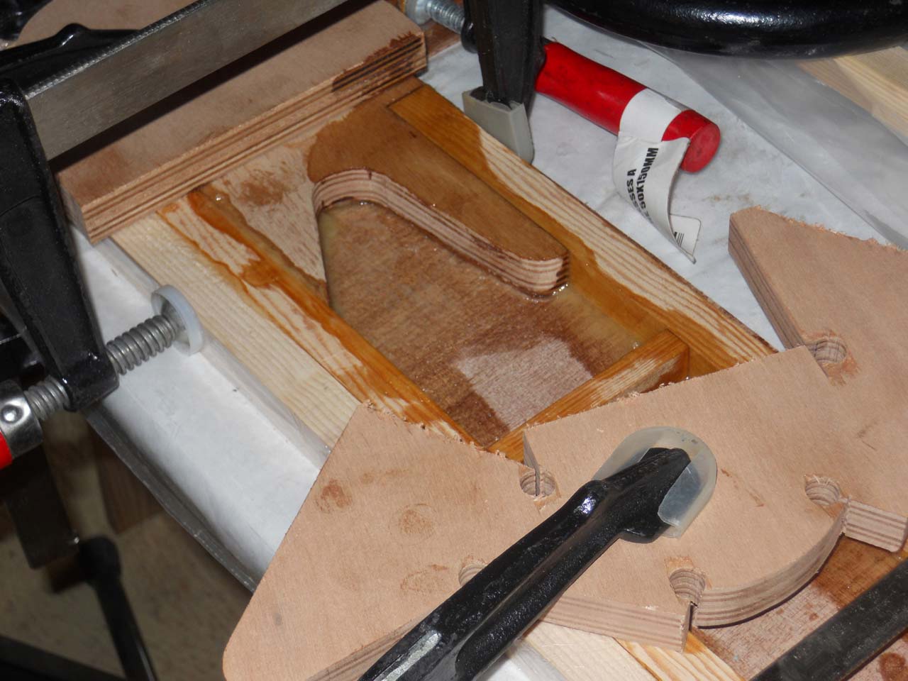
|
Wedge
|
| Some frame pictures | ||||
C1 before gluing its last skin
|
C2 sticks and corners
|
C4 before gluing its last skin
|
C5 before gluing the last skin
|
C1 to C4.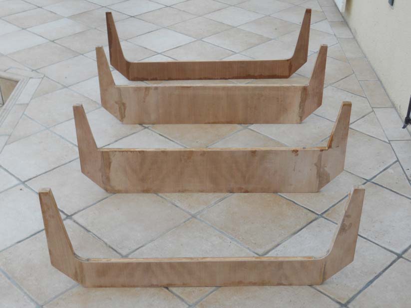
|
The firewall: it is a also a frame but its construction differs; not only because of its role but also because this is where the powerplant mounts and the front gear are attached. We start by jig sawing a pretty nice shape:
Template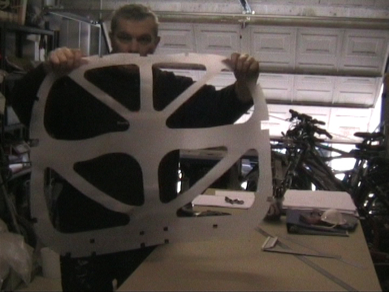
|
Drawing on plywood
|
Jig sawing
|
|
|---|---|---|---|
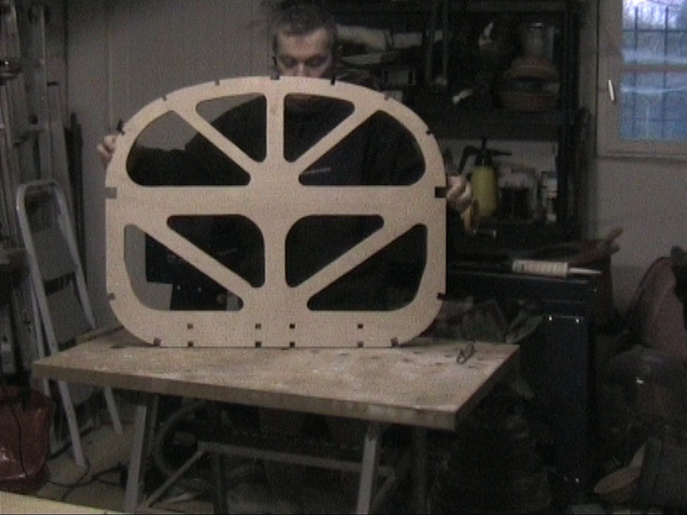
| Framework completed. | |||
|

|
||
When the firewall frame is completed, the first skin is glued one one side, then the holes are filled with AIREX (aeronautical foam) and eventually we close the firewall with the second skin.
| Gluing the firewall AIREX and skins. | ||
|---|---|---|
| Drawing the AIREX fillers | Cutting the Fillers

|
|
Drawing... sonny is going about it

|
Done... room optimized.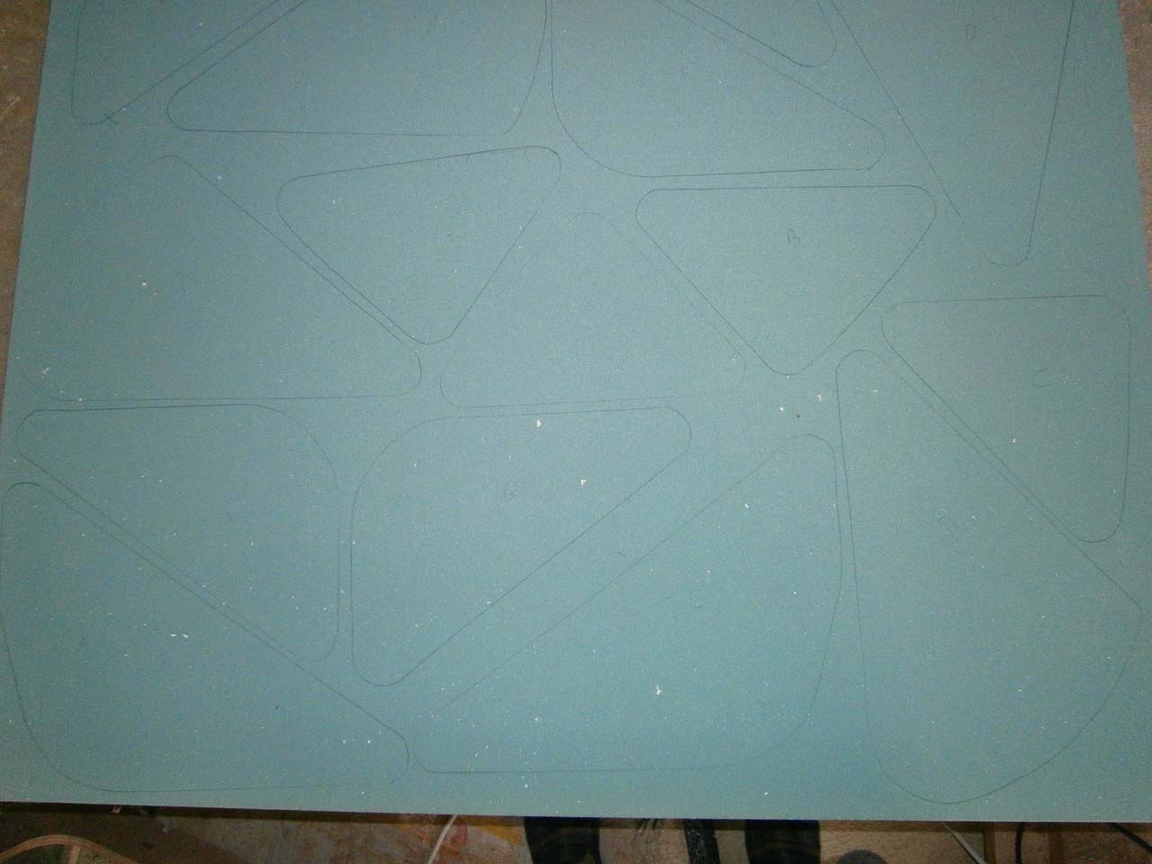
|
|
Gluing the AIREX Fillers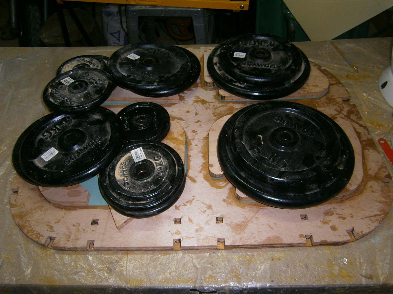
|
Fillers glued
|
Secong sking gluing.
|
Putting the structure together: The structure is placed
on a construction bench and then glued. Mine is made with boards
I took on old pallets (thank you Marc!) that I planed to the same
thickness. The boards are screwed on metal corners laying on trestles.
The frames are first blank mounted in order to position wedges holding the main longerons
parts when they will actually be glued. The longerons are made of laminated
wood (Oregon pine rods).
My Oregon pine beam was a bit short in length (about one inch), I could
not find a longer one. I cut and glued the rod with a bevel to lengthen
it. I needed one at the front (shown on the picture) and one at
the rear. The front one is in between 2 other rod, and the rear
one is located under a beech wedge (C10); so they are both reinforced.
| Bench and gluing the main stringer. | |||
|---|---|---|---|
| Construction bench | Main Stringer gluing. | ||
Overview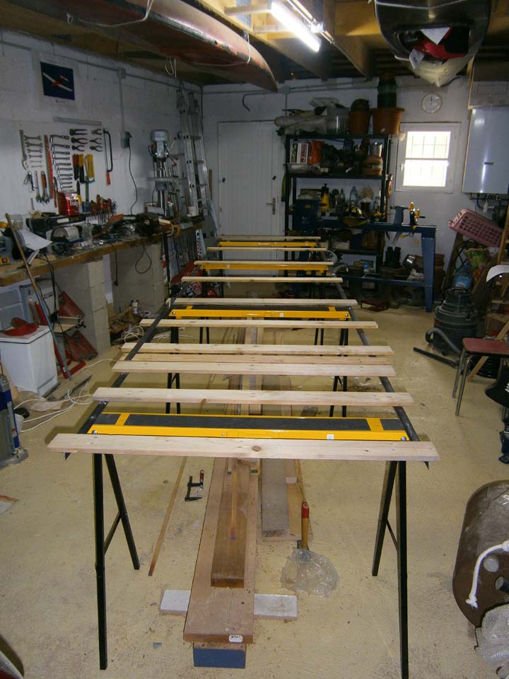
|
Stringer wedge
|
Seen from firewall
|
Seen from the rear
|
Bevel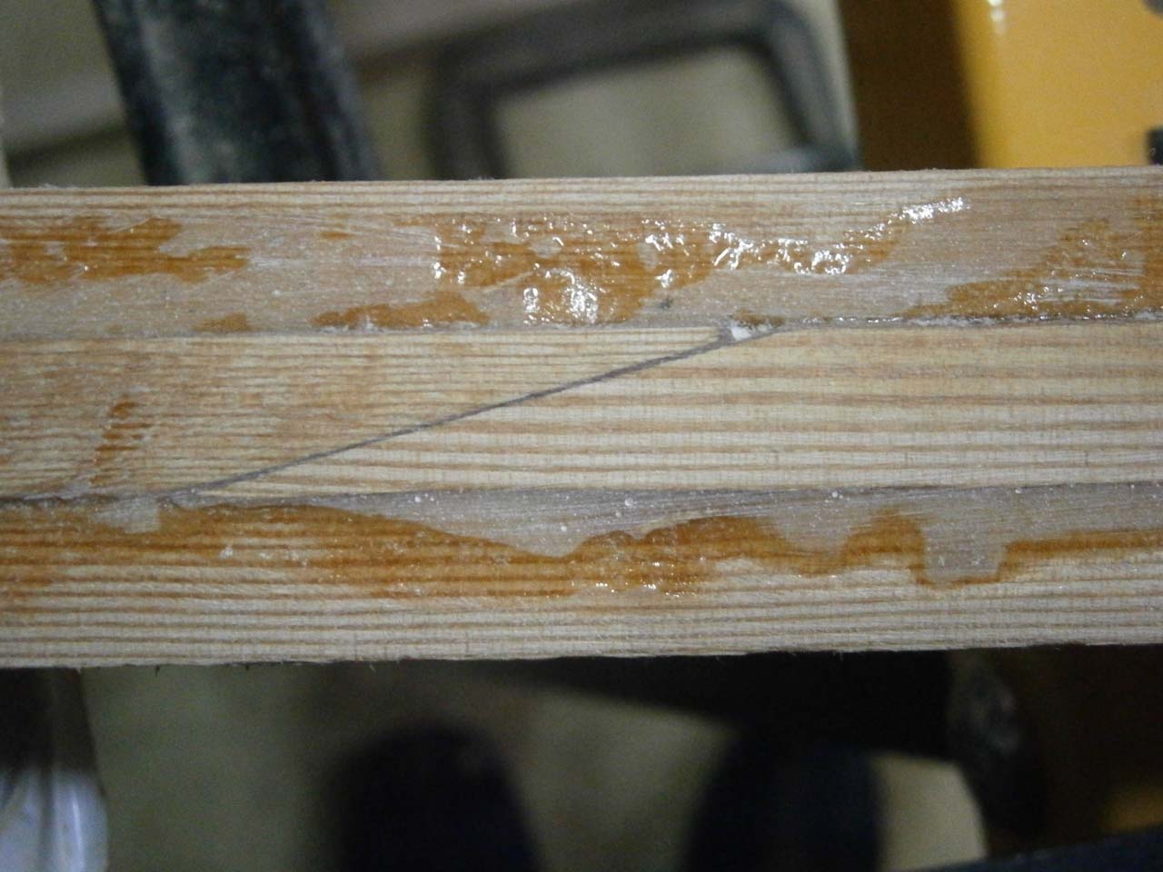
|
Detail
|
||
Gluing the frames: Once the longerons lamination is completed, it is time to go about the frames. The plane is upside down which ensures the flatness of the main longerons. The 45° longerons are then glued.
| Gluing the frames and the 45° longerons | |||
|---|---|---|---|
| Frame and lower 45° longerons | Upper 45° longerons | ||
Rear View
|
Frong View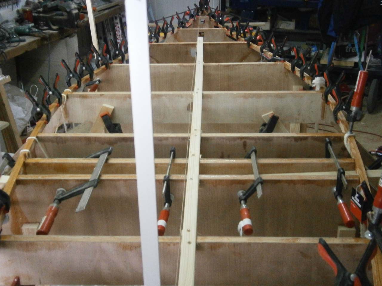
|
Seen from the firewall
|
Right Side
|
Global view
|
Global view the the False spars.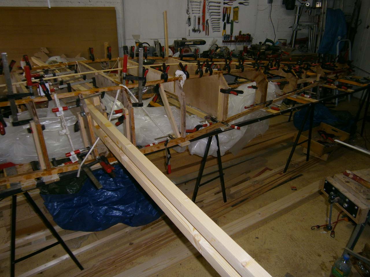
|
Detail of the 45° longerons being glued.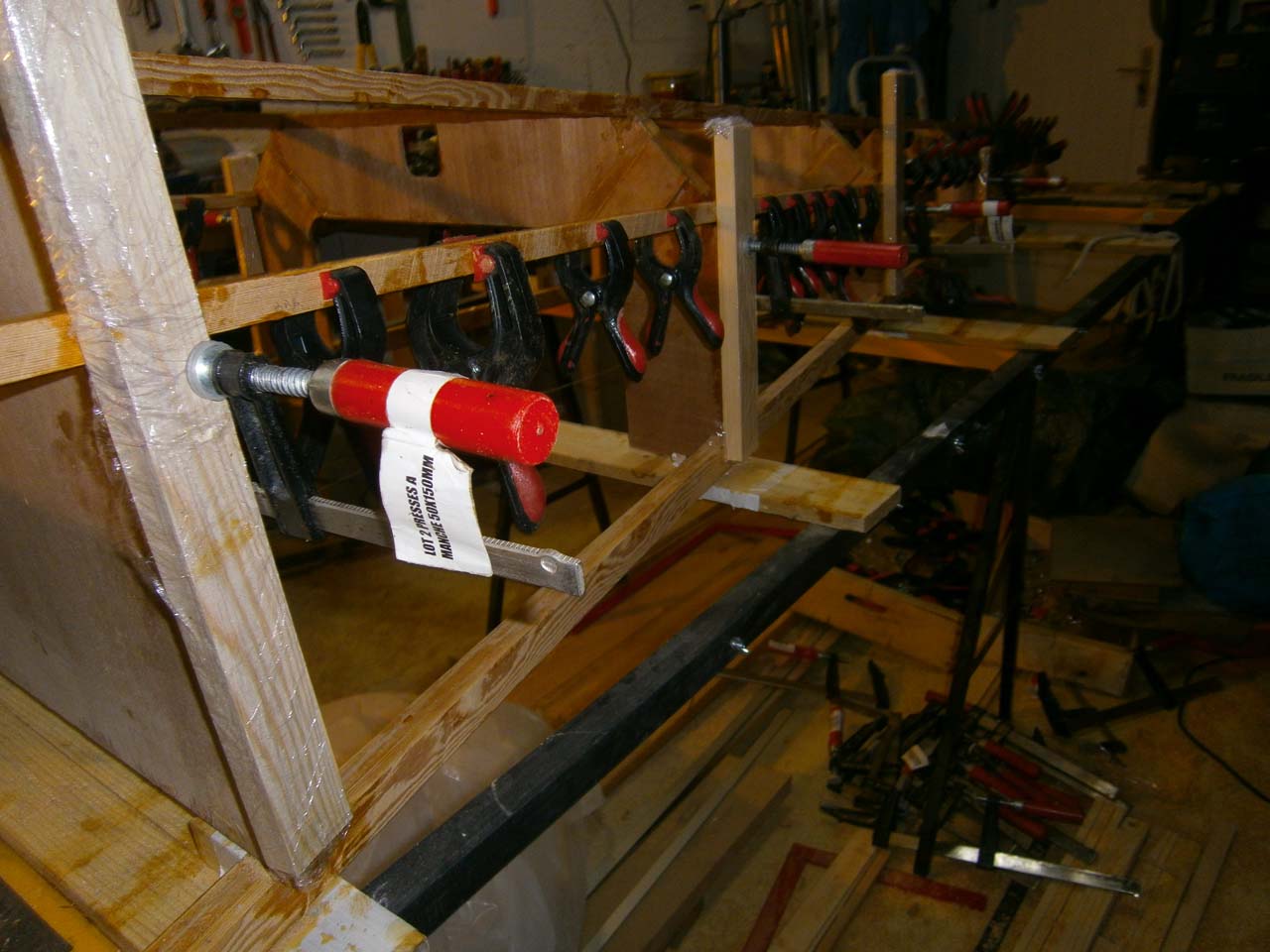
|
|
Planing the frames and the 45° longerons:
frames and 45° longerons should now be planed to provide the skins an optimal gluing surface.
Before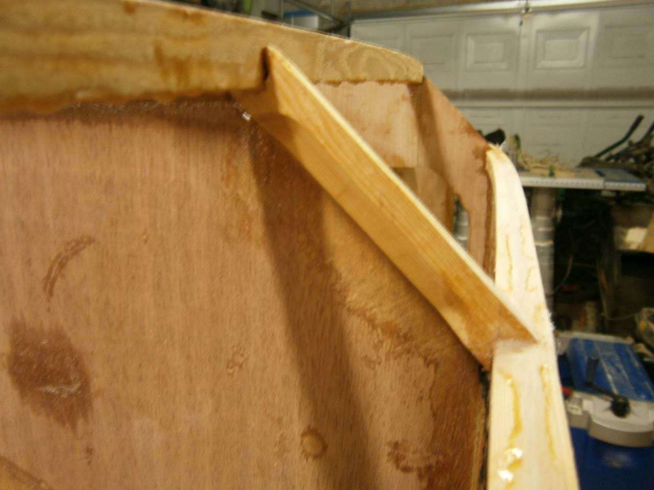
|
After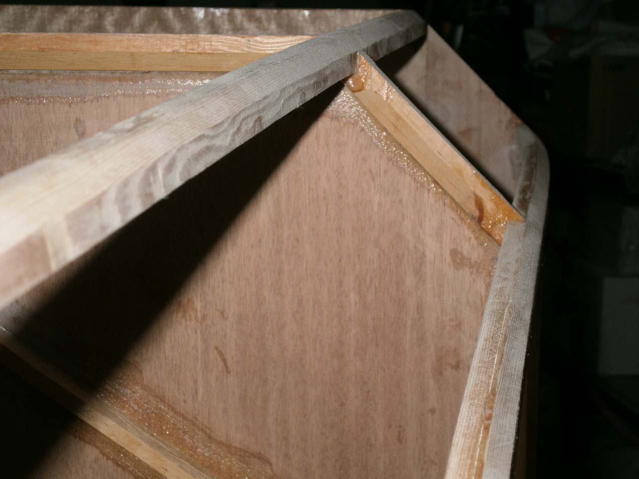
|
||||
|---|---|---|---|---|---|
| Framework ready for its skins | |||||
Global view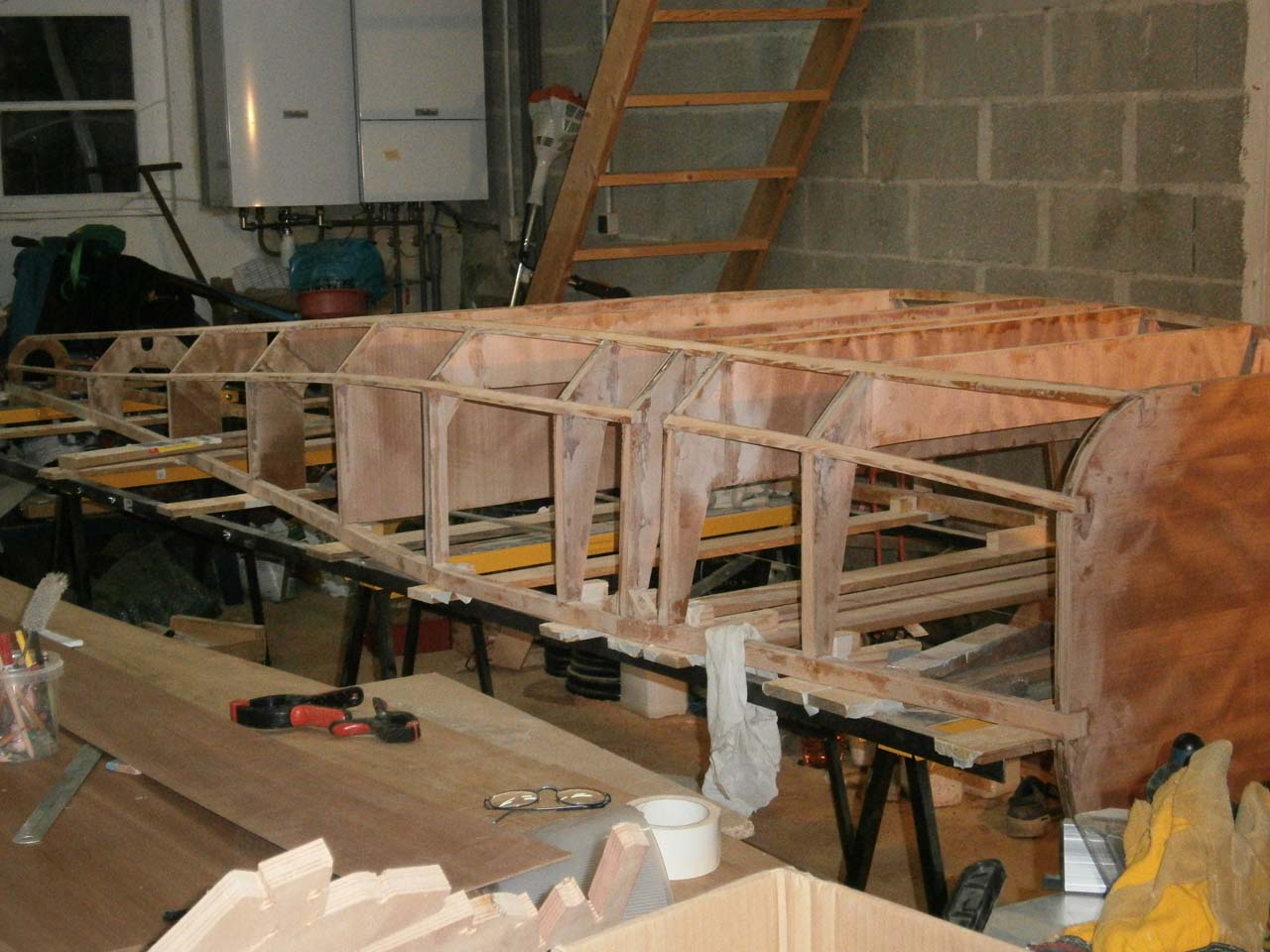
|
Rear view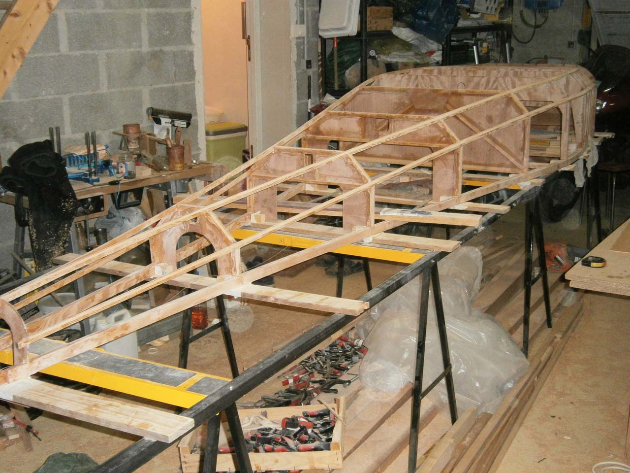
|
Seen from the firewall.
|
|||
Skins gluing:
Once the the framework is completed and the corners planed, it time to
go about gluing the skins.
Fred's trick to remove the stapples.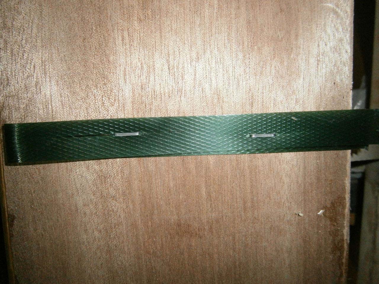
|
Another trick pretty much like Fred's one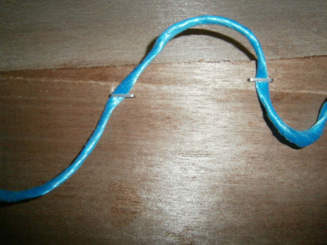
|
||
|---|---|---|---|
| 45% bevels | |||

|
|
|
|
| lower and side skins | |||
|

|

|
|
Top skins: We can now flip the "boat" right-side-up...
|

|

|
|---|
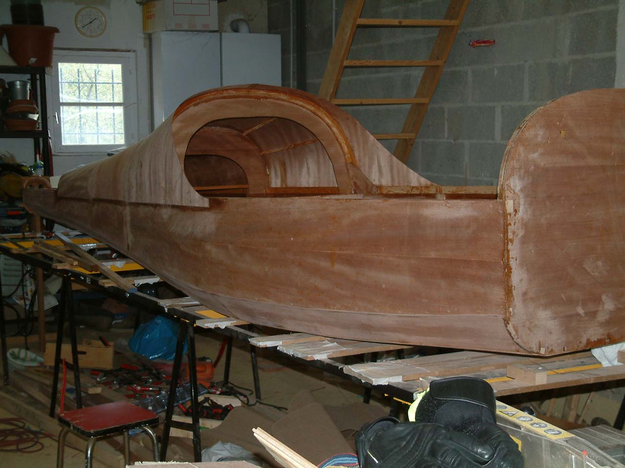
Manufacture of the top formers:The formers are made of a bow glued on a
plywood sheet. The bow for C6 is glulam when the other ones are plywood. For C6 the plywood sheet is not glued
until C6 is glued on the fuselage, this makes its positionnning much easier.
WARNING: To bend the parts hold them in shape from outside
the wedges, it makes you life easier and the risk of breakage is way lower; do not do like shown below, it
worked but I had to go very smoothly. Well sometime your brain cells are out of order !!!
C6 (cannopy former) lamination
|
C6, C7, C8 et C9 bows
|
C7, C8 et C9 formers
|
|---|
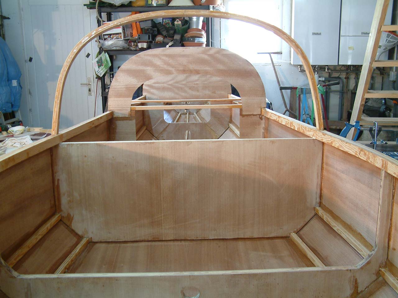
Top formers gluing:
C6 requires lots of precision; it is the cannopy former.
Stick to the dimensions on the plan and wedge
firmly. The "string" is used to flex the bow so it
perfectly fits in place. A set of wedges are used to
maintain C6 to the correct angle.
| Gluing | ||
|---|---|---|
C9
|
C6 (canopoy frame)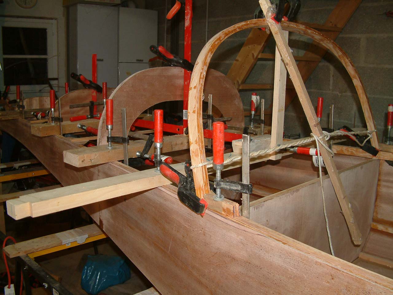
|
C6 (Angle)
|
| Done. | ||

|

|
|
Bottom stringers: We seize the
opportunity to have an easy access to the bottom of the
fuselage to strengthen it by gluing stringers.
Between C4, C5 and C6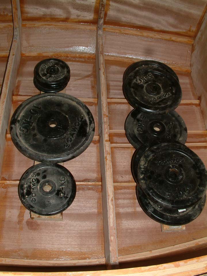
|
Front Stringers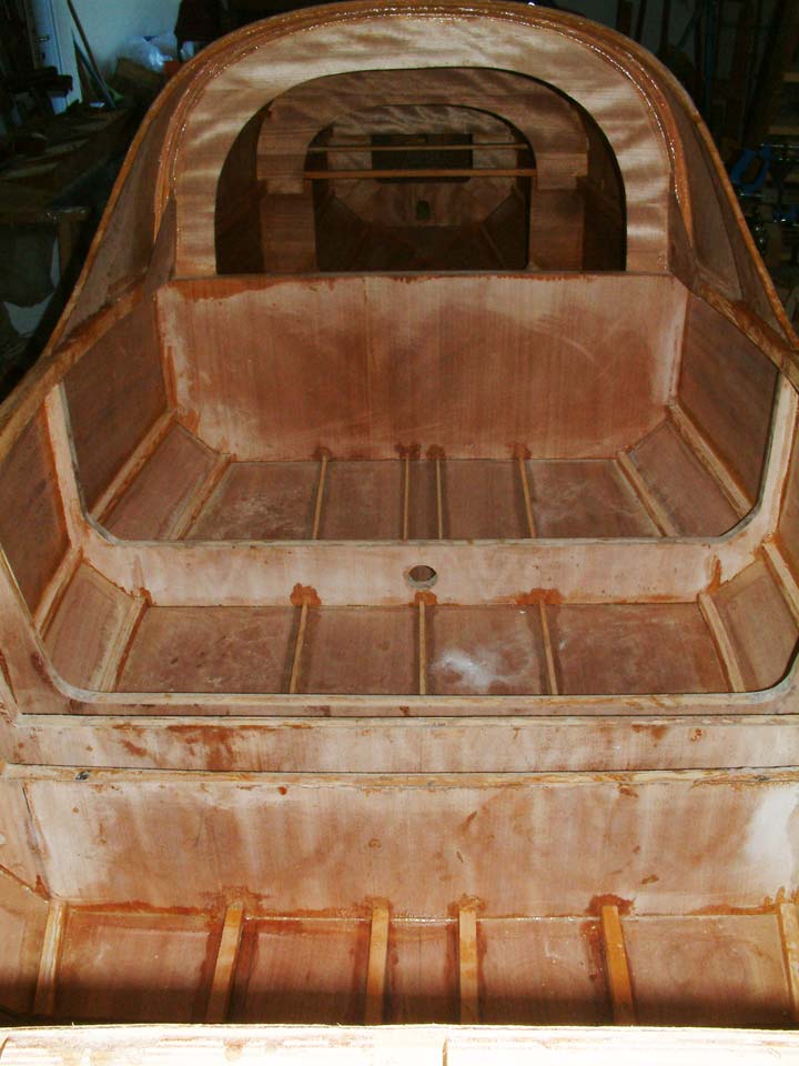
|
Between C6, C7, et C8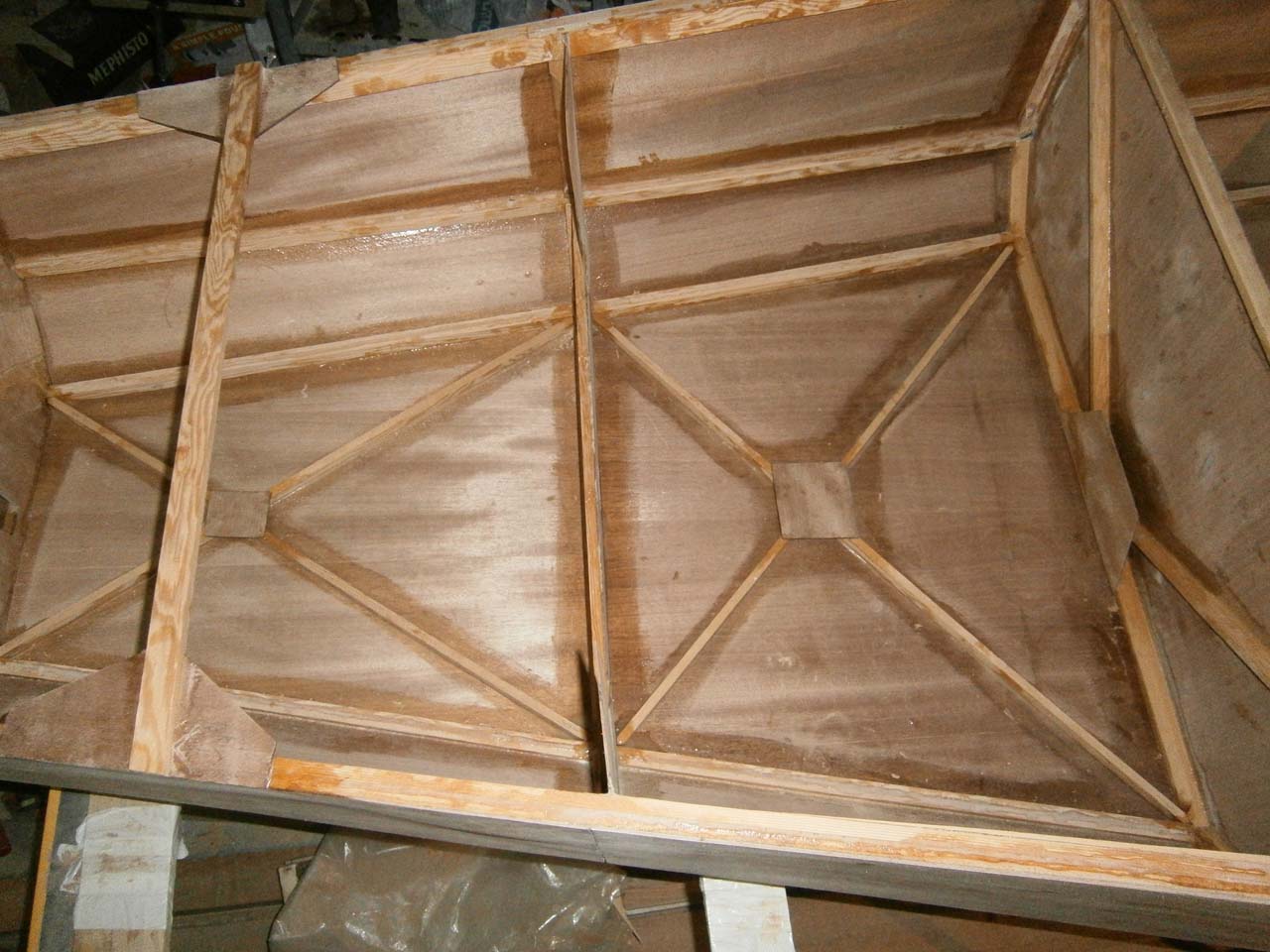
|
|---|
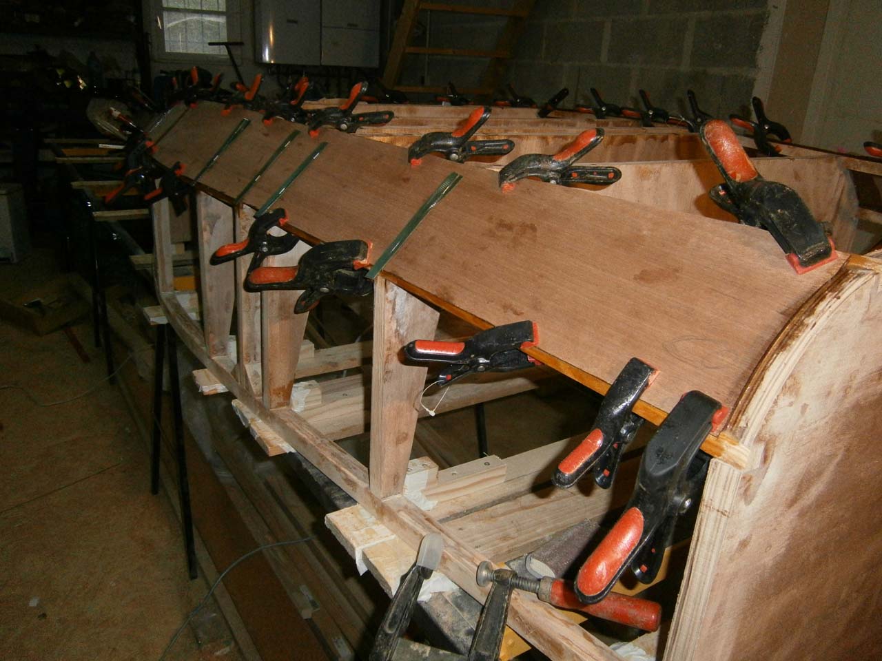
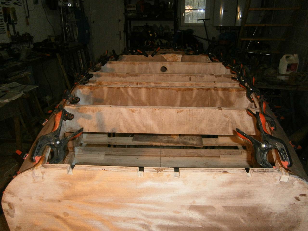
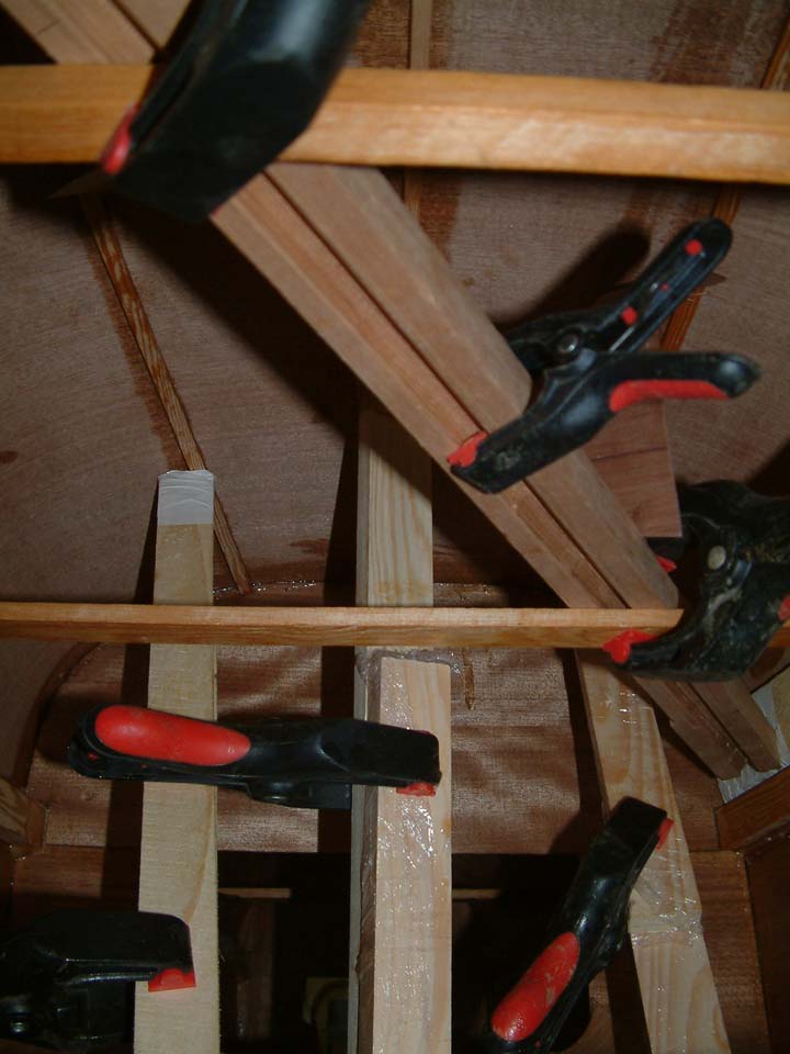
Gluing the top skins:
staples and straps are used to firmly hold the plywood sheets against the frames and longerons. Once the skins
are glued, they must be reinforced by adding pine stringers. These stringers must be glued AFTER the
bonding of the skin to maintain a smooth shape, if they were glued before they would create bumps and ugly edges.
We do not yet glue the skins between C9 and C10: this is the location of the vertical stabilizer, and will work in this area.
Finally we put a gusset on each side on C6 and the main longerons.
| Gluing the skins | |||
|---|---|---|---|

|
|

|
|
| Gluing the stringers. A tangle of props! | |||

|
 |
||
| Done! | |||

|

|
|
|
Reinforcing the skin for the canopy: We have to make 3 glulam. The first one in made in place by gluing rods against the skin from one longeron to the other. The 2 others have to be bentin 2 directions and therefore cannot be made in on shot. These 2 glulam are made larger that the final dimension, once in place they will be put to shape (this gives the second bend direction). This time, I put the parts on the right side of the wedges: way easier! When the glulams are glued on the skin we close the triangles they make with a gussets.
Glulam "kit" 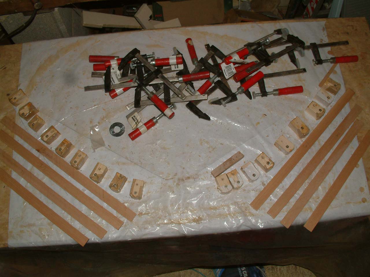
|
Laminating the bows 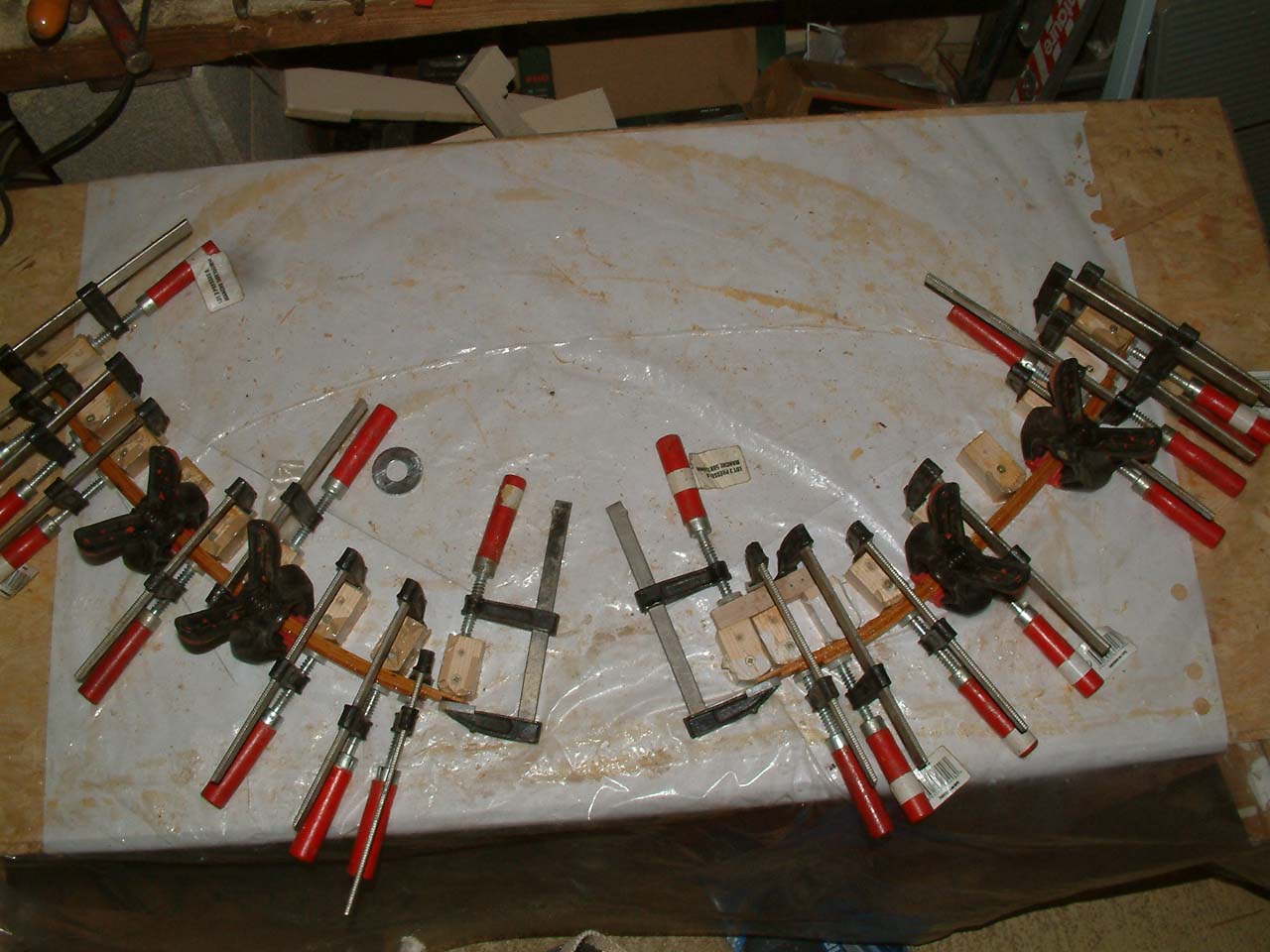
|
Small glulam before putting it to shape. 
|
Glulam in place: The triangle will be closed by gussets.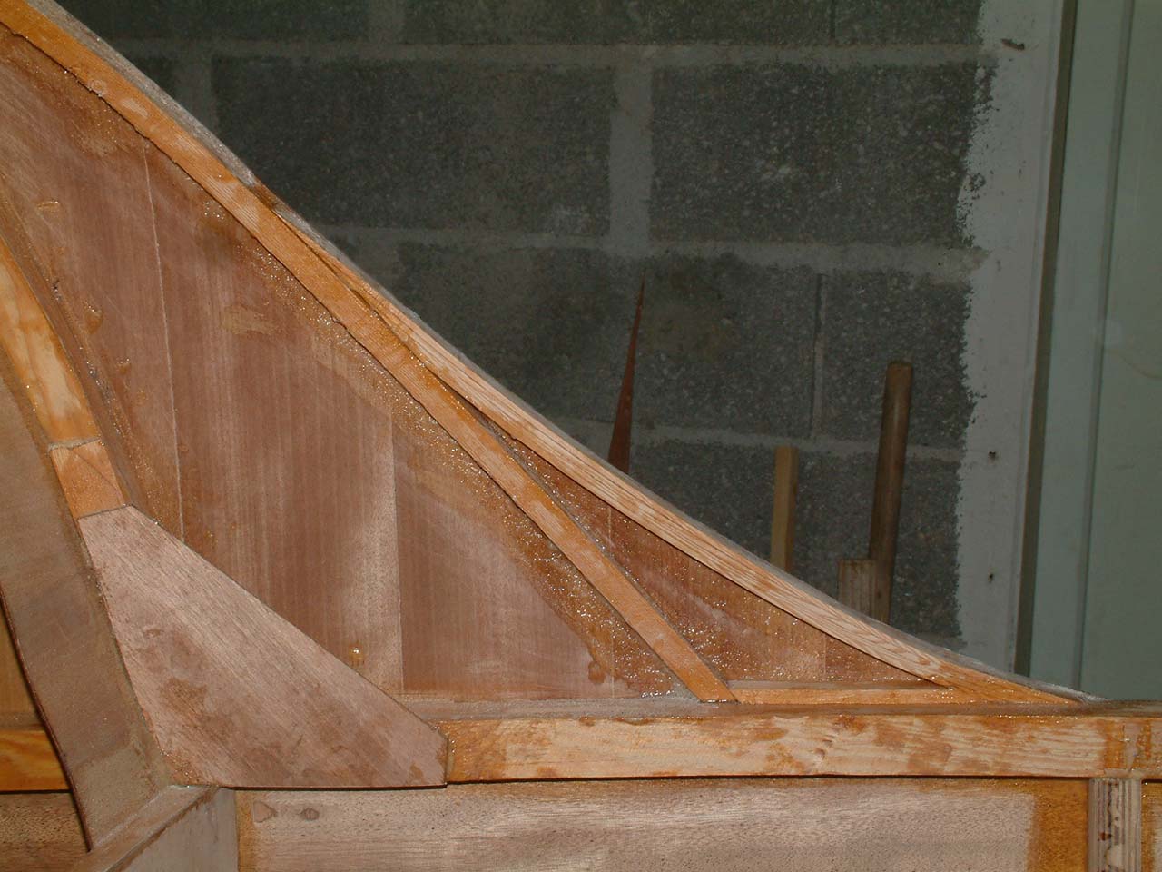
|
|---|---|---|---|
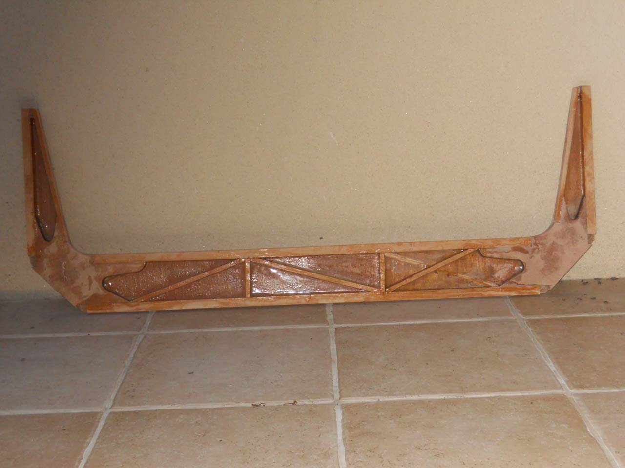
Done with the gussets glued.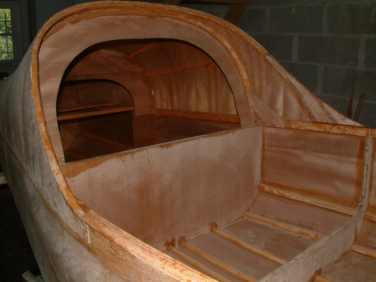
|
|||
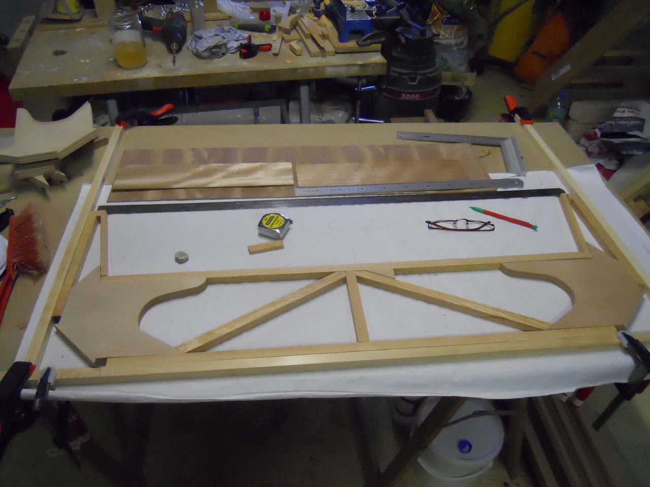
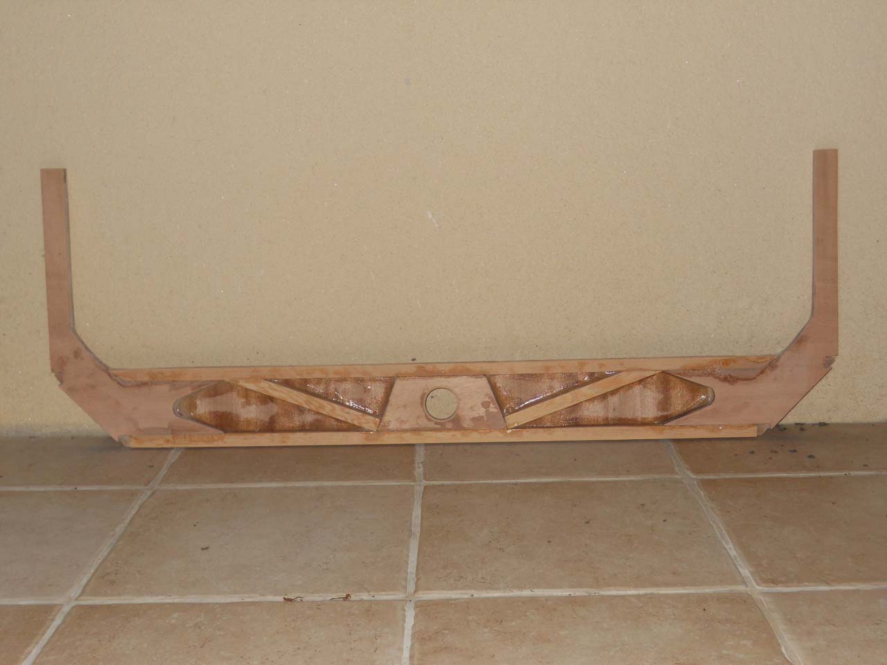
Floor and rudder bearings: The floor beams are made with pine rods and a plywood sheet glued on one side reinforce the assembly. 3 beech wedges are glued at the location of the bearing screws. Eventually the floor itself is glued on the top of the assembly.
Gluing the Beams and Stringers.
|
Beams glued.
|
Gluing the plywood sides 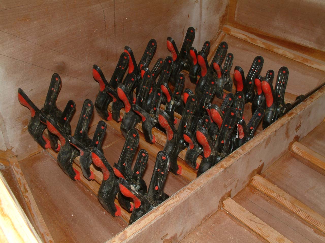
|
Gluing the beech wedges to screw the rudder bearings.
|
|---|---|---|---|
Rudder bearings.
|
Floor.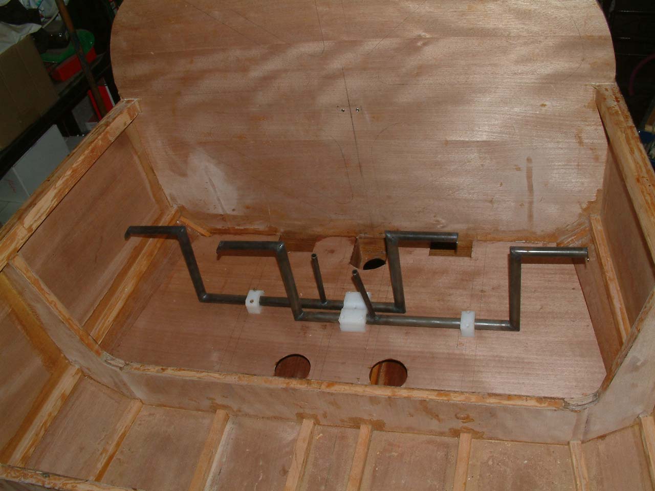
|
||
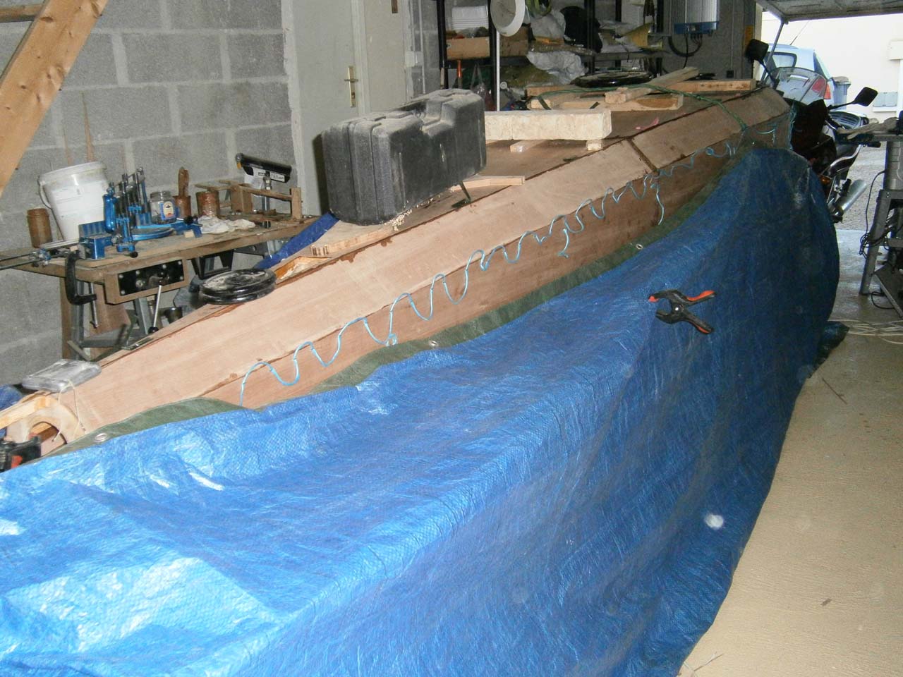
Assembly of the vertical stablizor and the stabilator:
- Vertical stabilizer:
Its leading edge is glued between two rods on C9. At the rear, the 2 rods that extend
the spar are fixed on the 45° bottom skins. The rear assembly is reinforced by a "false frame" made
of pine rods and plywood.
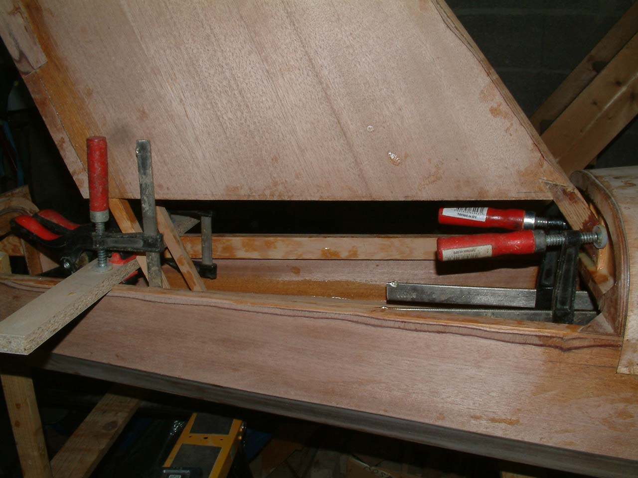
- The stablilator: it is temporarily positioned on C10 using clamps and a wedge
(gives the correct spacing). The beech wedges allow to mount the fittings parallel one each other
because the sides of the fuselage are not. This positioning makes it possible to check the beech wedges parallelism and
then counter-drill them together with the fuselage. We take the opportunity to
trace the shape of the fitting on the beech wedge which will then be shaped and glued.
Gluing the vertical stabilator
|
Leading edge on C9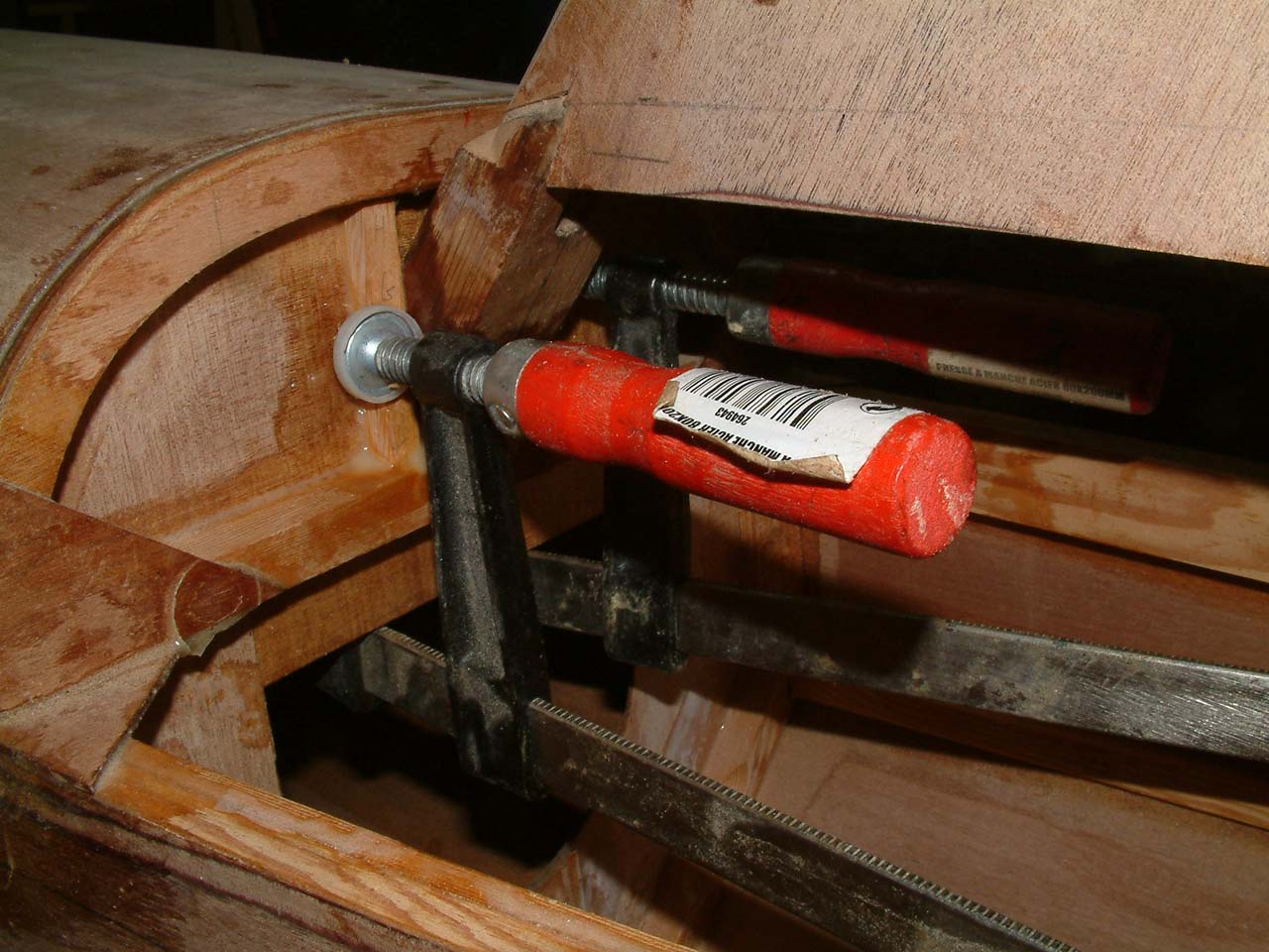
|
"false frame" (rear view)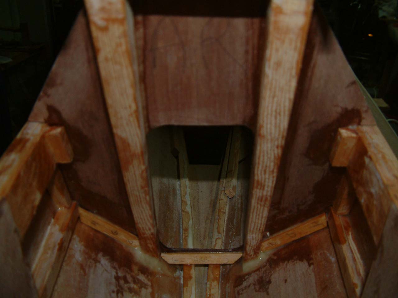
|
There you go!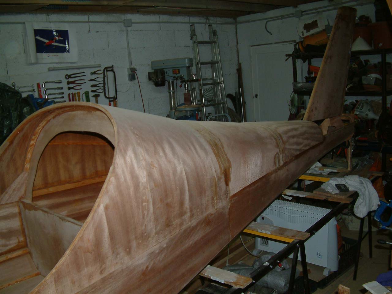
|
|---|---|---|---|
| Stabilator | |||
Positionnig with a wedge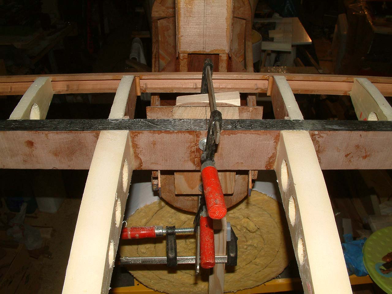
|
Ready to counter-drill
|
Front view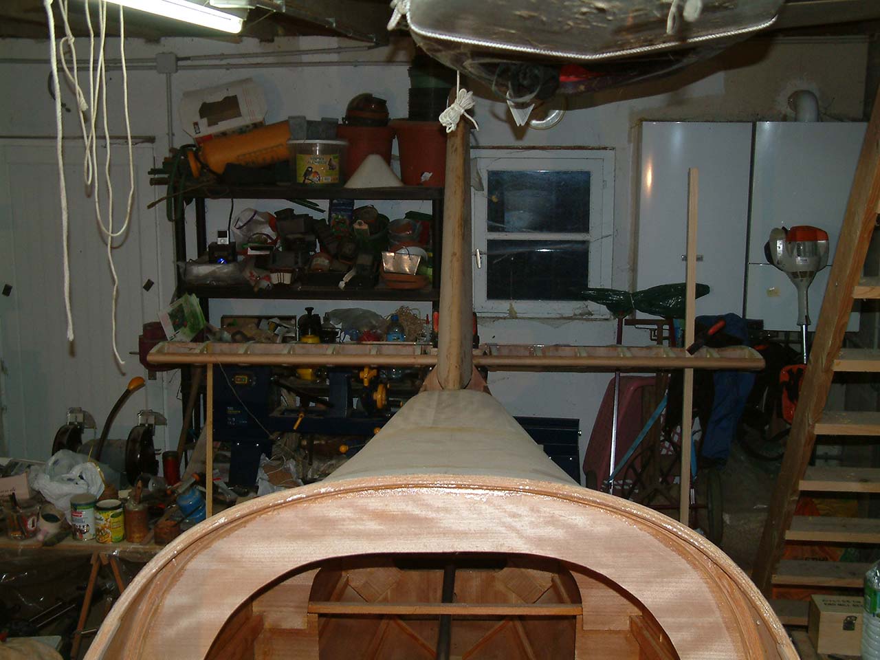
|
Rear view.
|
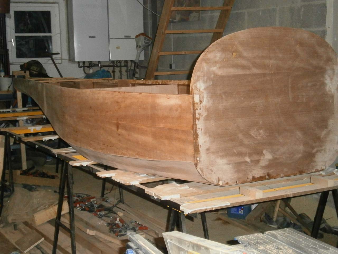
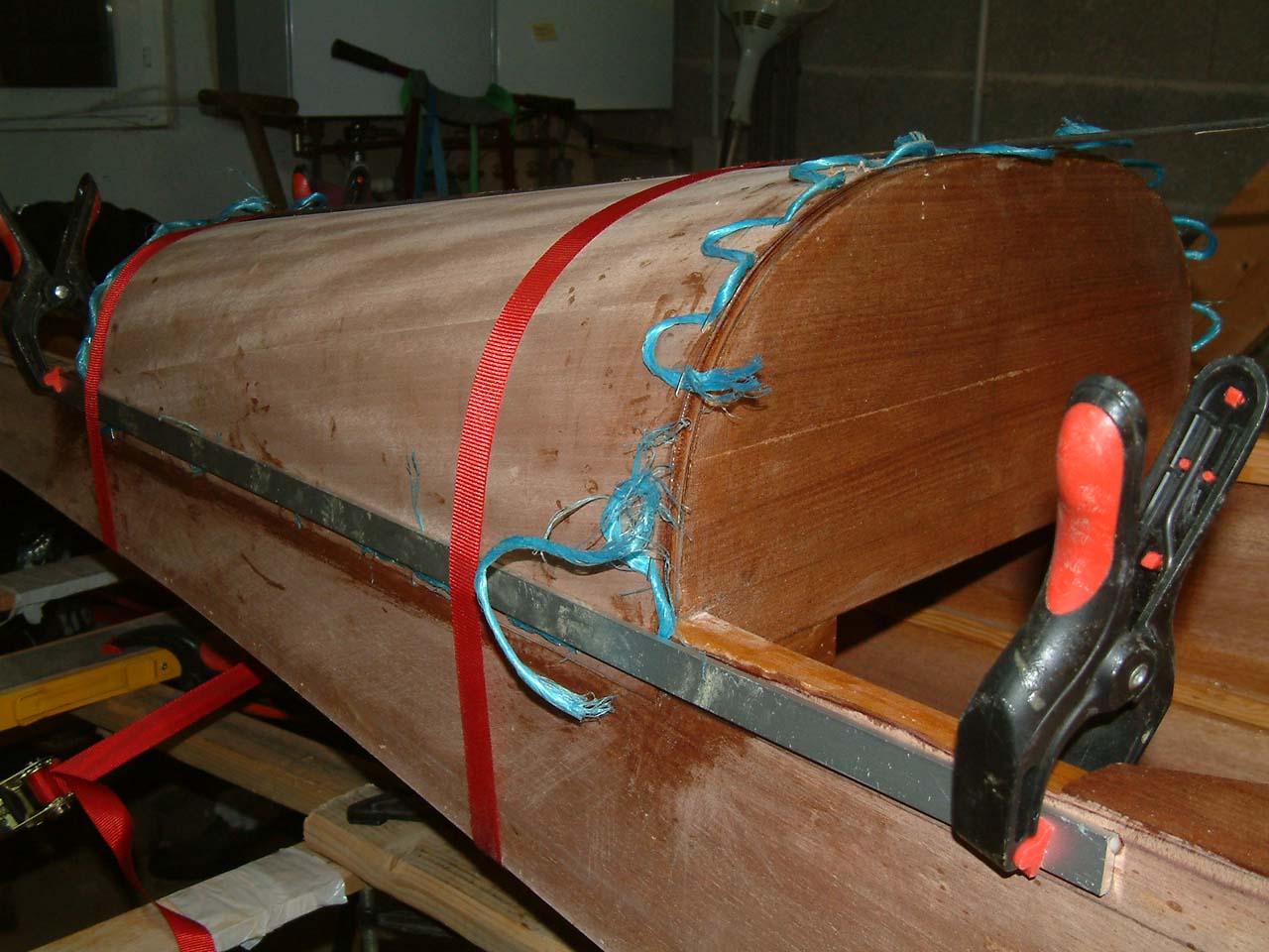
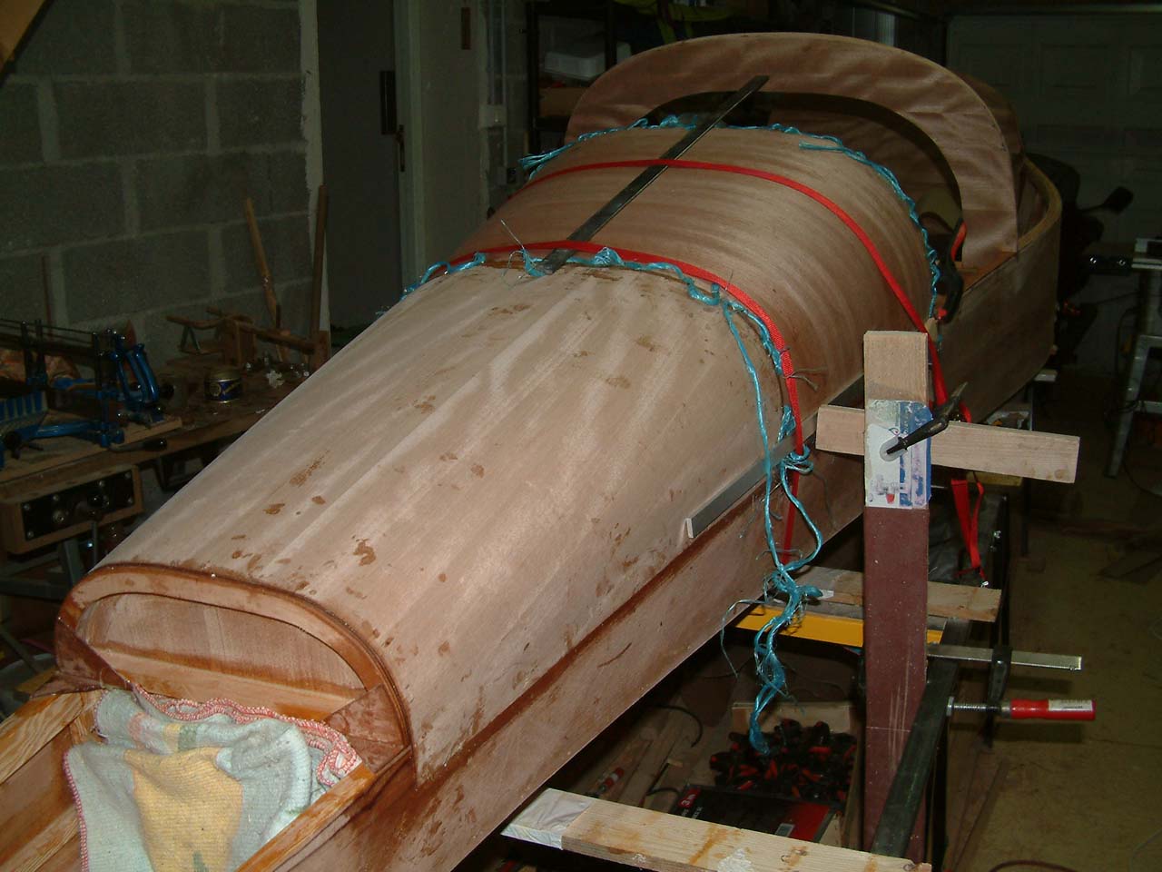
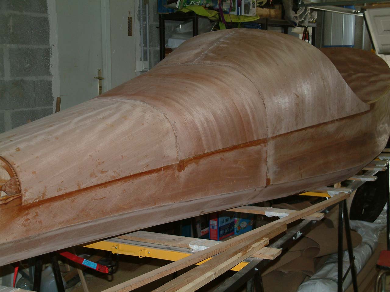
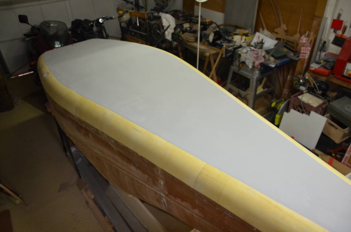
Rounding off the "chines" (45° sides): First glue large ofextruded polystyrene
on the 45° sides of the fuselage with straps. Then cut roughly with a handsaw, then with a rasp and finish with
a strip of sandpaper.
Since the plane is up side down, this is a good oppourtunity to put a layer of fiber glass, putty,primer and paint.
| Gluing Extruded Polystyrene boards. | |||
|---|---|---|---|

|

|
||
| Sawing the foam. | Rasping the foam. | ||

|

|

|

|
Ready to paint
|
|||
| Sanding | |||
| First one | Second and last | ||

|

|

|
|
Painted |
|||